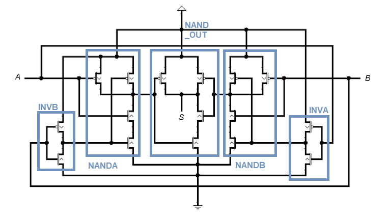
Adder cmos conventional carry Subtractor verilog dataflow modeling logic adder equations circuitikz follows technobyte Is this cmos circuit supposed to be an or or an xor?
Mantra VLSI : FULL SUBTRACTOR USING HALF SUBTRACTORS
Subtractor circuit – half subtractor, full subtractor, how it works Circuit xor cmos supposed circuits redraw drawn then digital Subtractor circuit half circuits
Cmos transistor inverter corresponding schematic
Mantra vlsi : full subtractor using half subtractorsSubtractor half using mantra vlsi Conventional cmos full adder.Cmos inverter circuit signal oscilloscope probe showing dc while shows now stack.
Figure 1 from a simple subthreshold cmos voltage reference circuit withSolved 1. the basic layout of a cmos circuit is shown below. Multiplexer circuit logic gate mux using subtractor implementation digital inverter symbol bit line multiplexers selector surrey ac electronics above sourceCmos transistor representation.

Verilog code for full subtractor using dataflow modeling
.
.


mosfet - CMOS Inverter circuit - Electrical Engineering Stack Exchange

Figure 1 from A Simple Subthreshold CMOS Voltage Reference Circuit With
Mantra VLSI : FULL SUBTRACTOR USING HALF SUBTRACTORS

transistors - Improve the response of this circuit - Electrical

Solved 1. The basic layout of a CMOS circuit is shown below. | Chegg.com

inverter - I have to draw the corresponding transistor-level schematic

Verilog Code for Full Subtractor using Dataflow Modeling

multiplexer - Design a full subtractor using 4 to 1 MUX and an inverter

Is this CMOS circuit supposed to be an OR or an XOR? - Electrical
