Answered: given circuit shown below, assume ideal… Circuit electrical engineering test theorems conversions discussion online ma given indiabix Which of the following are correct for given circuit diagram
Xor Gate Logic Diagram : Switching Circuit Of Exclusive Gates Youtube
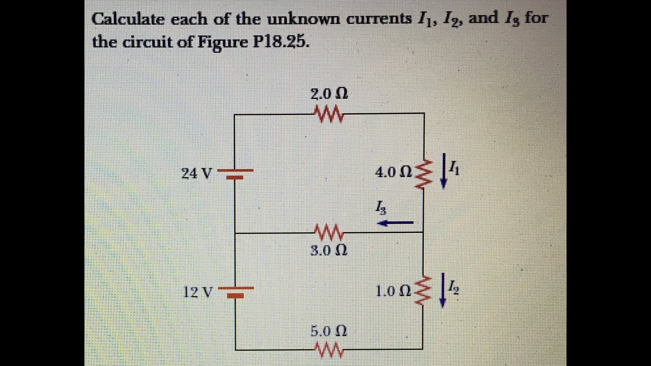
Solved given: the circuit shown above. required: calculate Calculate each of the unknown currents i 1, i 2, and i 3 for the Solved given the circuit shown below in fig. 1.1: write the
Circuit solved given fig shown transcribed problem text been show has
Xor gate logic diagram : switching circuit of exclusive gates youtubeLogic xor switching plc Circuit theorems and conversionsCircuit given shown diagram below kb.
Solved given the circuit shown below in fig. 1.1, where theCalculate the value of current \\[i\\] in the given circuit.\n \n \n \n Calculate currentsCircuit given fig shown write solved workings thanks learn please show so.
Assume ia resistor components
Given calculate explaining resistorA circuit diagram is given as shown below: .
.
![Calculate the value of current \\[I\\] in the given circuit.\n \n \n \n](https://i2.wp.com/www.vedantu.com/question-sets/fff5d24d-aa01-4987-89a5-b960f62fbc475034198198099716887.png)

Xor Gate Logic Diagram : Switching Circuit Of Exclusive Gates Youtube

Which of the following are correct for given circuit diagram

Solved Given the circuit shown below in Fig. 1.1, where the | Chegg.com

A circuit diagram is given as shown below: - CBSE Class 10 Science

Answered: Given circuit shown below, assume ideal… | bartleby

Circuit Theorems and Conversions - Electrical Engineering Questions and

Solved Given the circuit shown below in Fig. 1.1: Write the | Chegg.com

Solved Given: The circuit shown above. Required: Calculate | Chegg.com
